
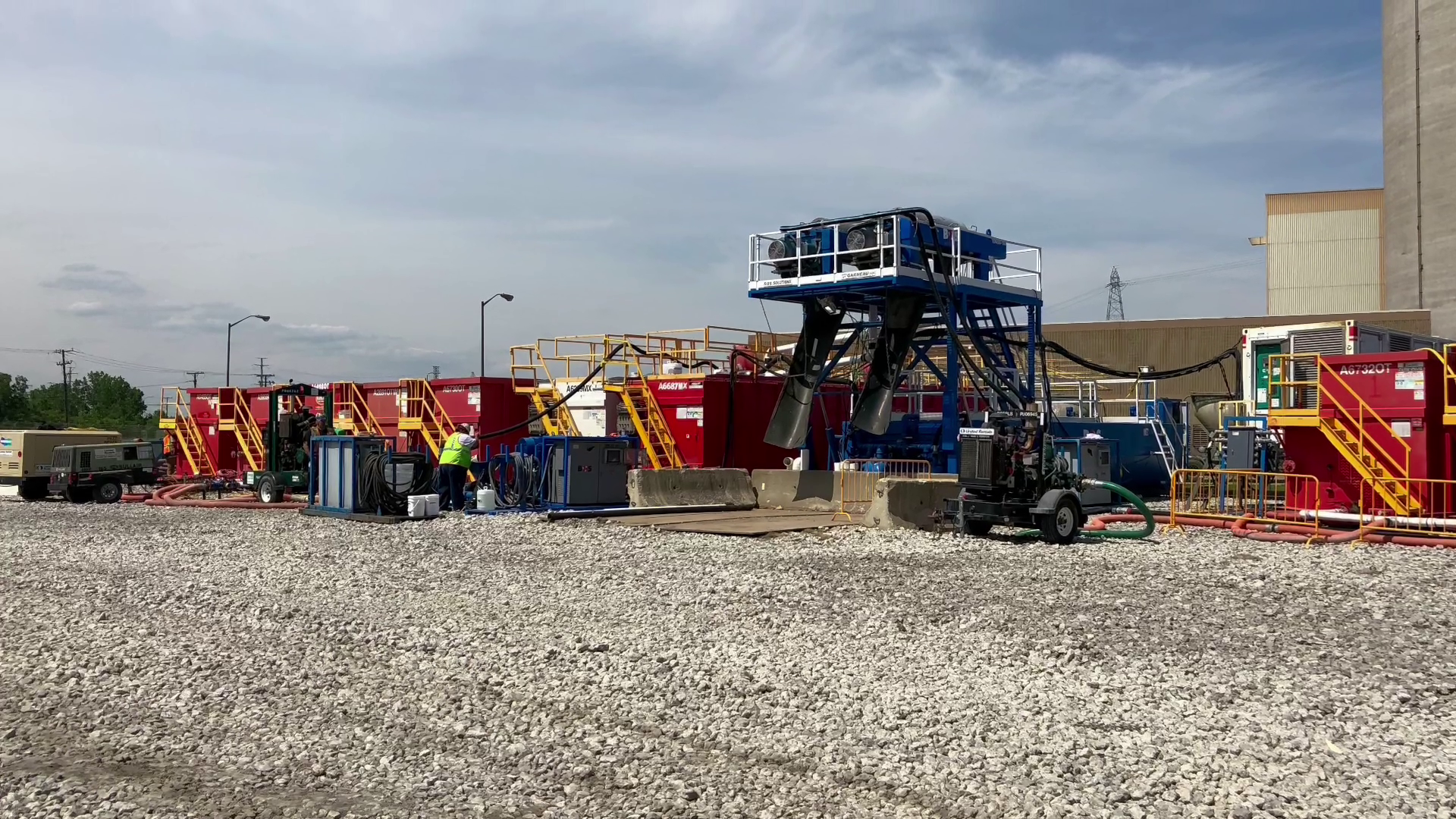
Two large-bowl centrifuges ran the fluid loop, operated by one technician who also mixed polymer to spec.
Case study | Construction slurry management
Polymer drilling fluid recovery for the Gordie Howe International Bridge
The numbers behind the loop
What one technician and two centrifuges kept moving.
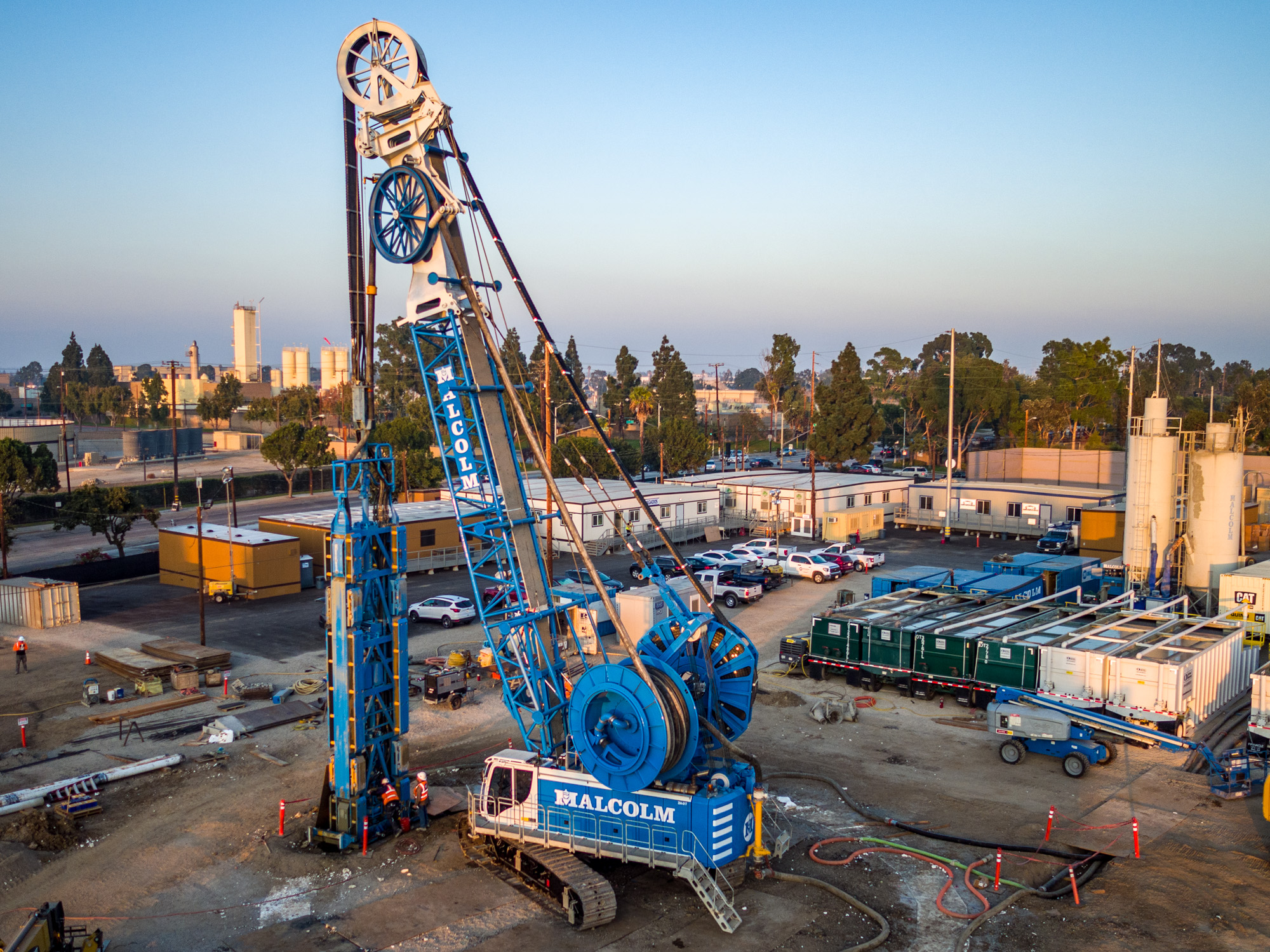
BOS Environmental Solutions, now Stage 3 Separation (S3S), provided slurry management for the polymer drilling fluid used in cased, drilled shafts on the Gordie Howe International Bridge, a six-lane crossing spanning more than a mile and a half. The crew processed returned polymer daily, removed drilled solids, and pumped clean fluid back to the active shafts instead of disposing of it and mixing new batches.
Every figure here comes from the Gordie Howe International Bridge project, a six-lane, cased-shaft drilling program where the fluid had to keep working instead of getting replaced.
Each shaft used roughly 60,000 gallons (230 m3) of polymer fluid, recovered and returned rather than replaced.
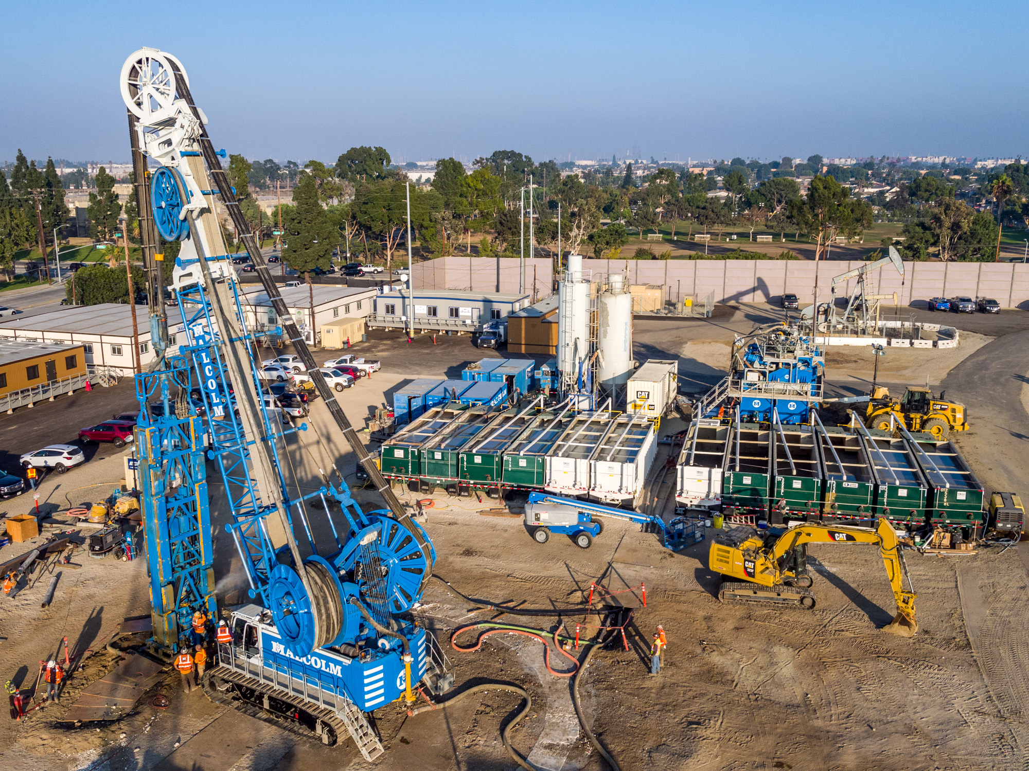
The crew built the fluid system on about ten 18,000-gallon tanks of polymer mixed to specification before drilling began.
Continued reuse of recycled polymer kept approximately 160,000 gallons (600 m3) out of disposal every two weeks.
Challenge, solution, result
A fluid system built to keep running, not get replaced.
Conventional settling tanks take days to drop out solids, and over time the solids go colloidal and stop settling at all. S3S ran a different system on the Gordie Howe International Bridge project.
Challenge
Settling tanks could not keep pace with 32 drilled shafts.
The bridge's cased, drilled shafts, 6 to 10 ft (2 to 3 m) in diameter and up to 120 ft (36 m) deep, needed a constant supply of polymer drilling fluid. Conventional settling tanks take days for solids to drop out, and over time the solids go colloidal and stop settling at all. The fluid gets heavier until it has to be disposed of. Settling also needs a much bigger footprint and segregated storage, which roughly doubles the polymer needed on the job.
32Drilled shafts on the six-lane bridge crossing
Solution
A closed loop of tanks, centrifuges, and one technician.
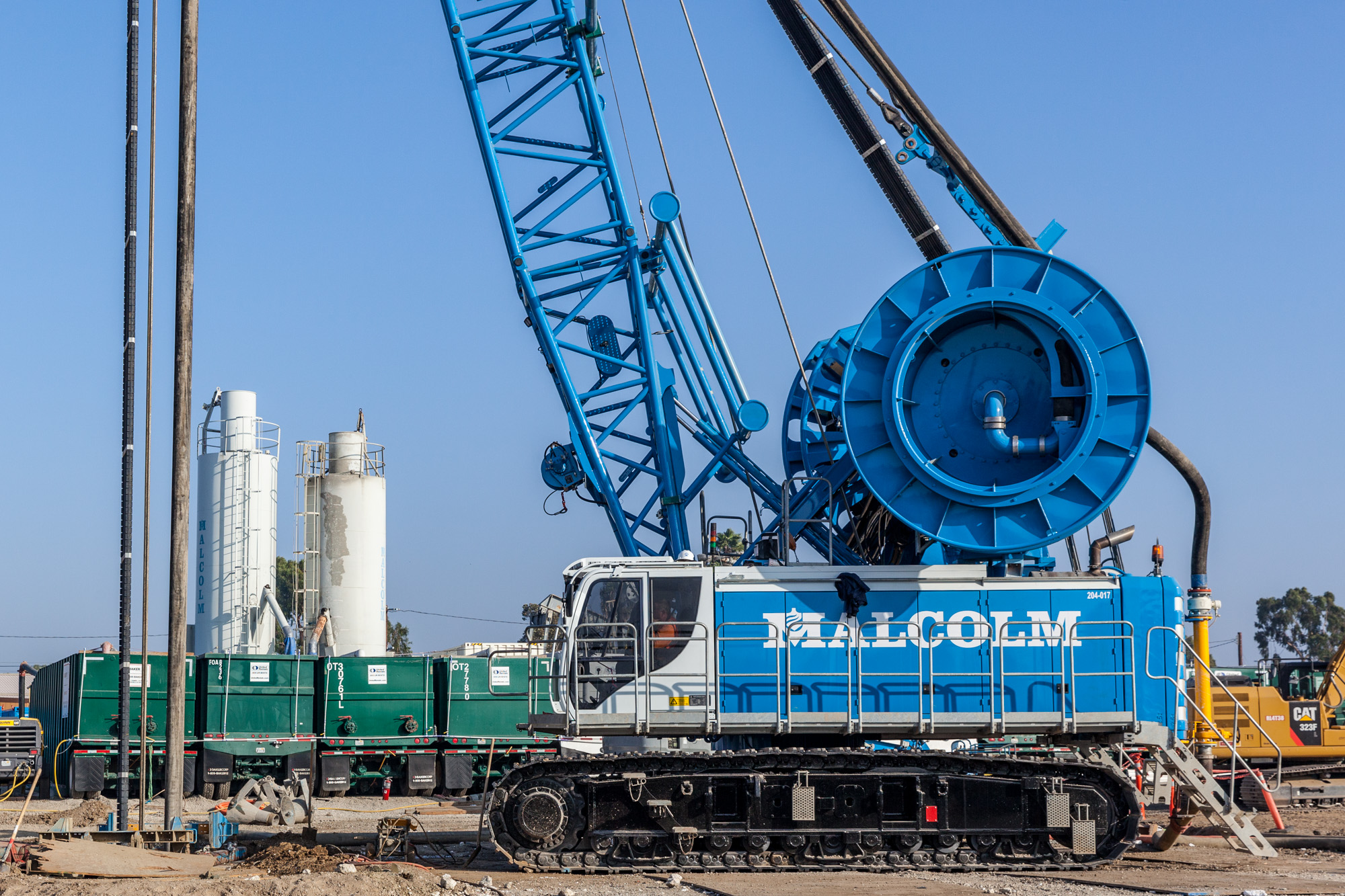
S3S built a BOS Tank system with two large-bowl centrifuges and staffed it with one technician who ran the entire fluid system: removing drilled clays, sands and silts from the polymer, and mixing fresh polymer to spec. Polymer returning from a shaft was pumped to a holding tank, processed daily, and the clean recovered fluid pumped straight back to the shaft for reuse.
2Large-bowl centrifuges run by a single onsite technician
Result
160,000 gallons of polymer stayed in the loop every two weeks.
Continued reuse of recycled polymer kept approximately 160,000 gallons (600 m3) from disposal every two weeks. Processed fluid left behind a solid, stackable, paint-filter-pass waste stream that went to a clean landfill, and onsite testing held the reused polymer to target rheology throughout. No vacuum trucks were needed on the project until the end, to clean the tanks before leaving site.
160,000 galPolymer kept from disposal every two weeks
The documented sequence
Move polymer fluid through a controlled reuse loop.
This sequence summarizes the published project configuration. It is useful as application evidence, not as a ready-made plan for a different drilled-shaft program.
01
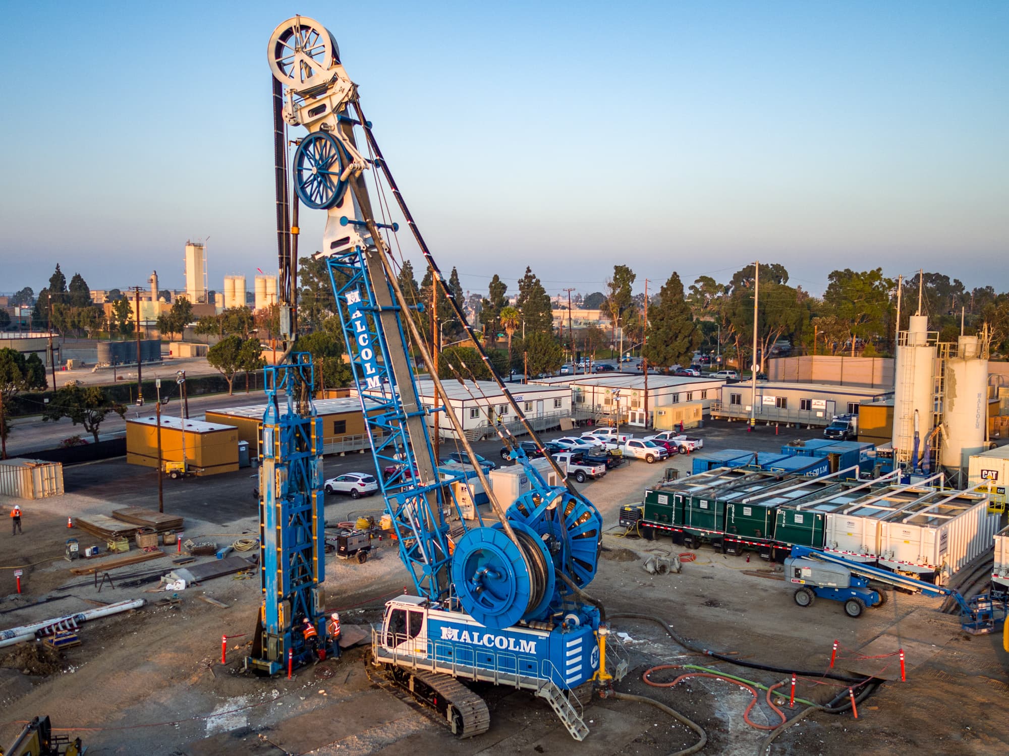
Build the starting fluid volume
The reported configuration began with approximately ten 18,000-gallon tanks of polymer fluid built to the project specification before the drilling sequence began.
02
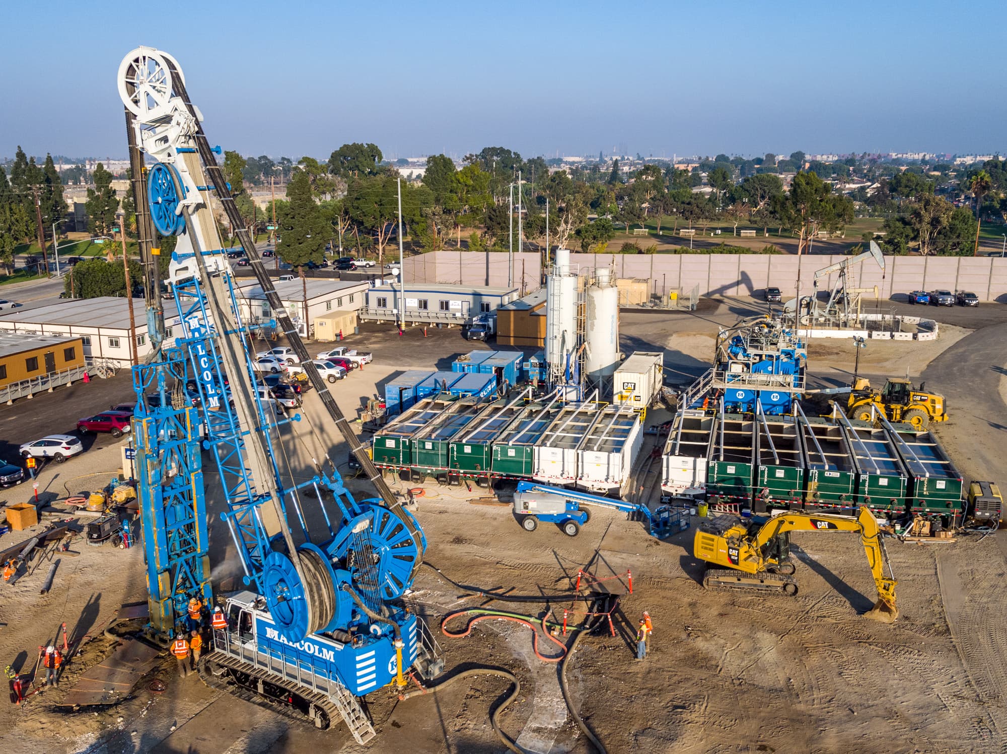
Receive returned fluid in holding tanks
Polymer returning from the shaft was pumped to holding tanks, creating a controlled point for fluid handling before solids separation and reuse.
03
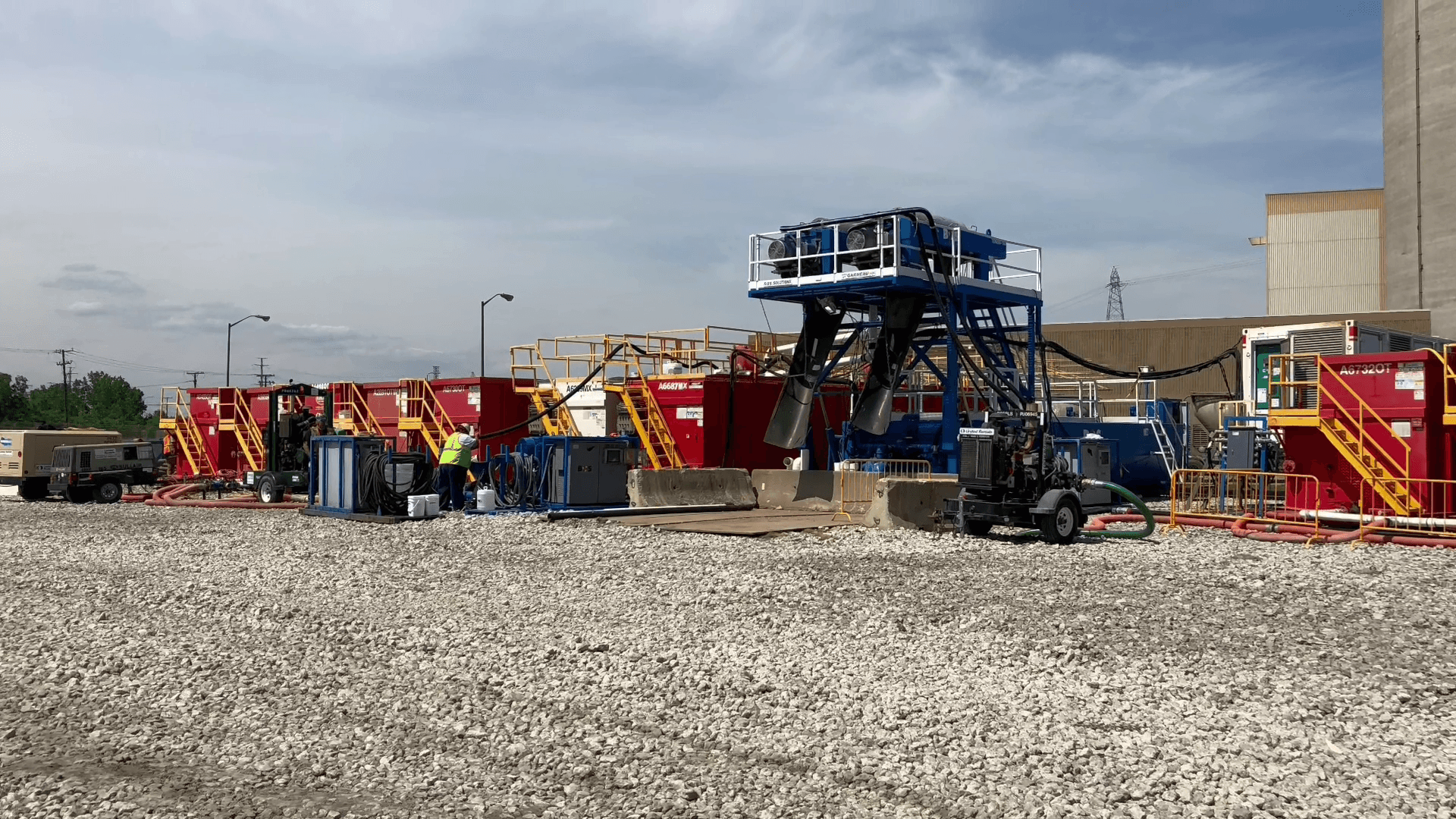
Separate solids and maintain the fluid
BOS tanks, two large-bowl centrifuges, polymer mixing, and onsite oversight were used to remove drilled clays, sands, and silts from the returned polymer fluid.
04
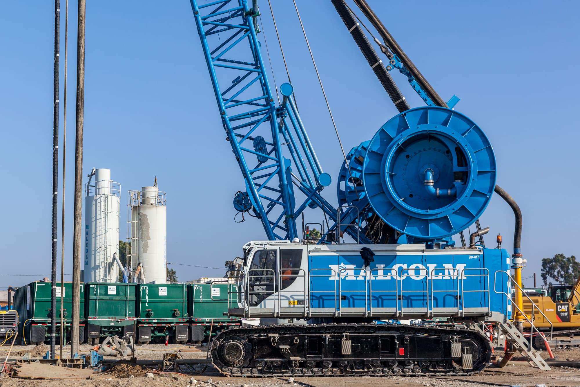
Return usable fluid and complete final cleaning
Recovered polymer was returned to the active work after onsite rheology testing. The account places vacuum-truck use at the final tank-cleaning stage before demobilization.
Work with S3S
S3S keeps drilled-shaft fluid working, not disposed of.
Tell us the fluid, the shaft program, and the site conditions. S3S will scope a treatment loop built for the job.
What happens next
- A separation specialist reviews the slurry, the expected flow and the site.
- We size the equipment and the crew against your schedule and the outputs you need.
- You get a configuration and a scope you can price the job against.