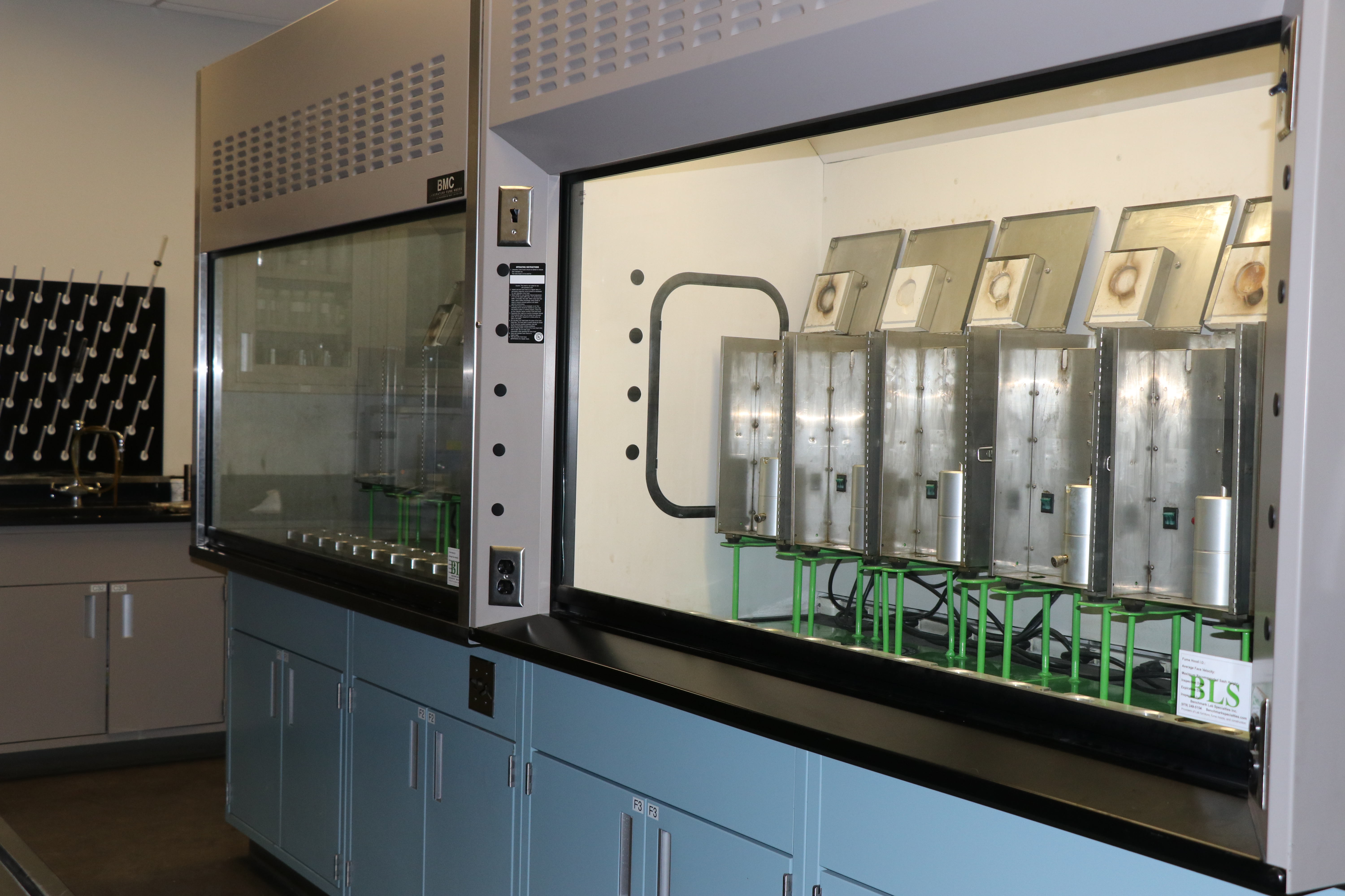
Characterize the feed.
Particle-size distribution, solids loading, variability, expected flow, and representative sample behavior determine what the plant must remove and protect.

Engineering approach
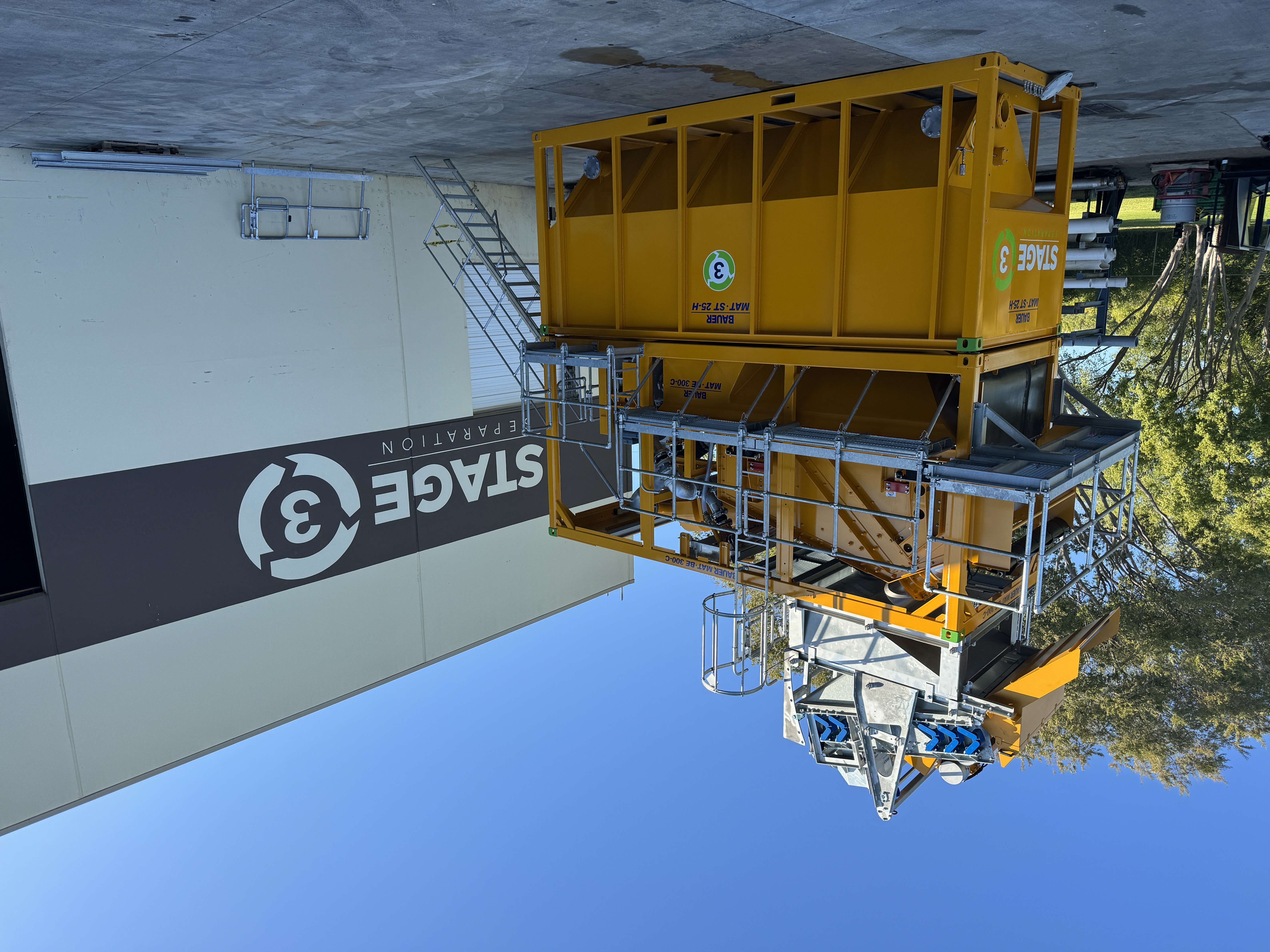
Before configuring a BE 300-C, S3S reviews the feed and particle-size distribution to decide how scalping, cyclones, dewatering screening, and the agitated tank fit. Power, footprint, access, fine-solids treatment, and the approved routes for water and solids are accounted for from the start.
Engineering inputs
The BE 300-C is a defined plant, but its role in a project still depends on the feed, required separations, site constraints, and the next step for both output streams.
Particle-size distribution, solids loading, variability, expected flow, and representative sample behavior determine what the plant must remove and protect.
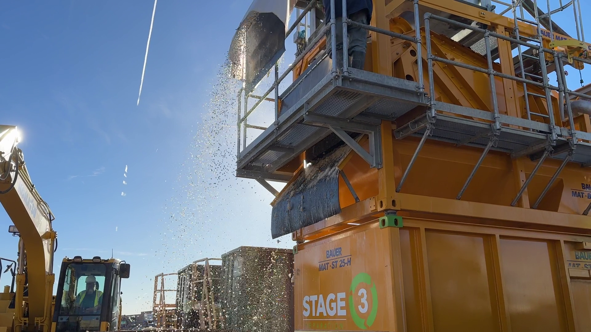
Scalping, 20-inch and 6-inch cyclones, dewatering screening, the agitated tank, and any fine-solids treatment are arranged around the actual material.
Power, access, installed footprint, lifting, supporting tanks, transfer, redundancy, and the approved water and solids routes shape the final configuration.
Plant building blocks
Engineering connects the documented plant components to the material and the project plan. The catalog maximum is a sizing input, not a promised field throughput or output quality.
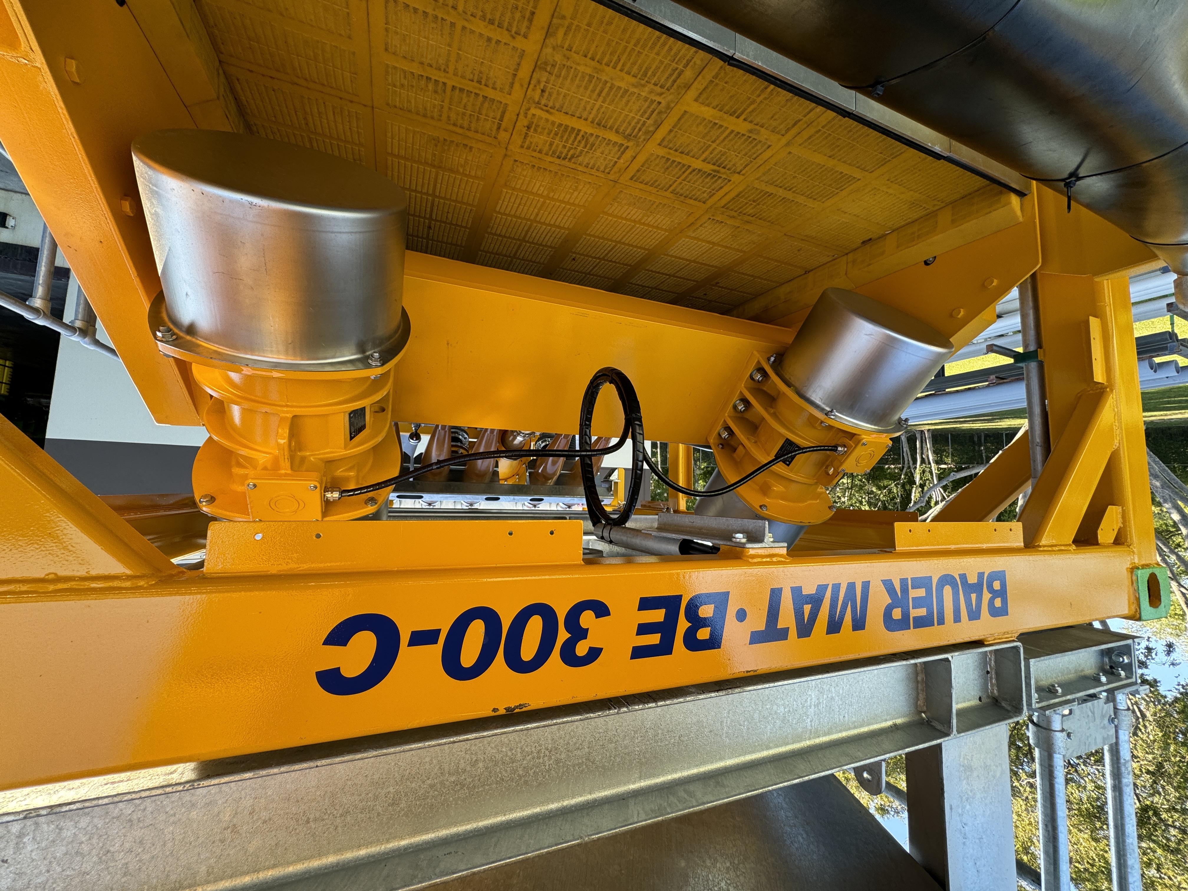
The adjustable scalping screen removes oversize material before 20-inch and 6-inch cyclone stages progressively address the remaining coarse fractions.
Engineering the deployment
Feed and particle-size distribution determine which fractions the BE 300-C can address directly, how each stage should be operated, and whether another fine-solids step belongs downstream.
A paired BE 600-C arrangement is evaluated when expected flow, operating flexibility, or redundancy requirements justify two units. Actual throughput still depends on the feed and configuration.
No. The project defines each output route through testing, applicable criteria, and receiver approval. The treatment train is configured to support that plan, not replace it.
Installed footprint, power, access, lifting, piping, supporting equipment, safe clearances, weather, operating crew, and downstream routing should all be resolved before mobilization.
Ready to take the next step?
S3S will review the material and project constraints, then map where the BE 300-C belongs in the complete treatment and operating plan.