
Instantaneous feed affects equipment and surge capacity. Total volume and duration affect whether mobilizing an onsite plant is commercially sensible.
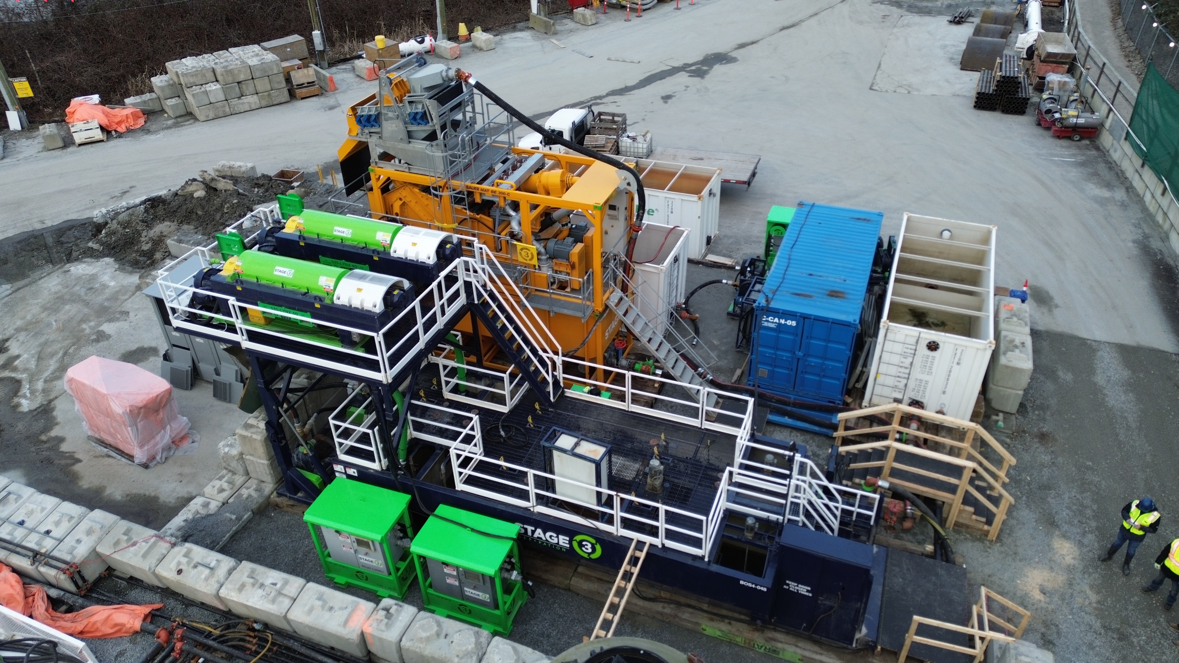
Slurry dewatering services
Engineer the waste stream before it controls the job.
Construction slurry does not become a manageable waste stream just because a centrifuge arrives onsite. The feed changes. Coarse material can overload downstream equipment. Fine clays may stay suspended. The separated liquid and solids still need defined, testable destinations.
Stage 3 Separation (S3S) scopes the complete path from incoming slurry to the required project outputs. We review flow and volume, particle profile, chemistry, site constraints, schedule, and the planned reuse, treatment, or disposal pathway. Then we configure and operate the separation train around the work.
Material before machine
The machine comes after the project inputs.
Slurry dewatering separates a solids-bearing liquid into a concentrated solids stream and a separated liquid stream. The useful question is whether it can do that at the required rate, on this site, into outputs that have an approved next step.
Particle size, concentration, density, mineralogy, additives, pH, and variability determine which stages can work and what should be tested.
Define reuse, further treatment, transport, testing, and receiving-facility requirements before selecting the final train.
Access, headroom, tanks, pumps, power, containment, hours, weather, solids loading, and truck movement shape the installed system.
Progressive separation
Remove the solids each stage can handle.
One device rarely does every job well. Engineered treatment moves from coarse protection toward finer separation, with each stage reducing the burden on the next. The exact sequence and cut points depend on the feed and outlet criteria.
StageCut PointRoleOutput
Feed controlVariable flowEqualize surges, keep solids suspended, and meter a stable feedControlled feed to the selected train
Scalping and screeningOversize materialRemove debris and consolidated solids before pumps and finer stagesScreenings plus protected slurry
Desanding and hydrocyclonesCoarse and intermediate solidsUse size and density differences to remove sand and silt fractionsLower-solids stream for reuse or further treatment
Conditioning, when requiredFine or difficult particlesUse tested chemistry and mixing to form separable flocsConditioned feed inside a verified operating window
Decanter centrifugeFine suspended solidsContinuously separate denser solids under centrifugal forceCentrate and concentrated solids for testing
Verification and routingProject criteriaSample both streams against the approved management planDocumented reuse, treatment, transport, or disposal decision
Equipment has a role
Build the process from coarse protection to fine separation.
S3S can combine screening, hydrocyclones, tanks, pumps, chemical conditioning, decanter centrifuges, controls, and field operation. The value is in selecting the stages that fit the material and keeping them balanced as conditions change.
Keep oversize material out of the fine-solids train.
Debris, gravel, and consolidated material can choke pumps, blind finer screens, disturb tank mixing, and accelerate wear. A scalping stage removes what downstream equipment should not be asked to process.
- Review
- Largest expected material
- Design around
- Screen area and bypass risk
- Watch
- Blinding and changing feed
- Route
- Screenings handling pathway
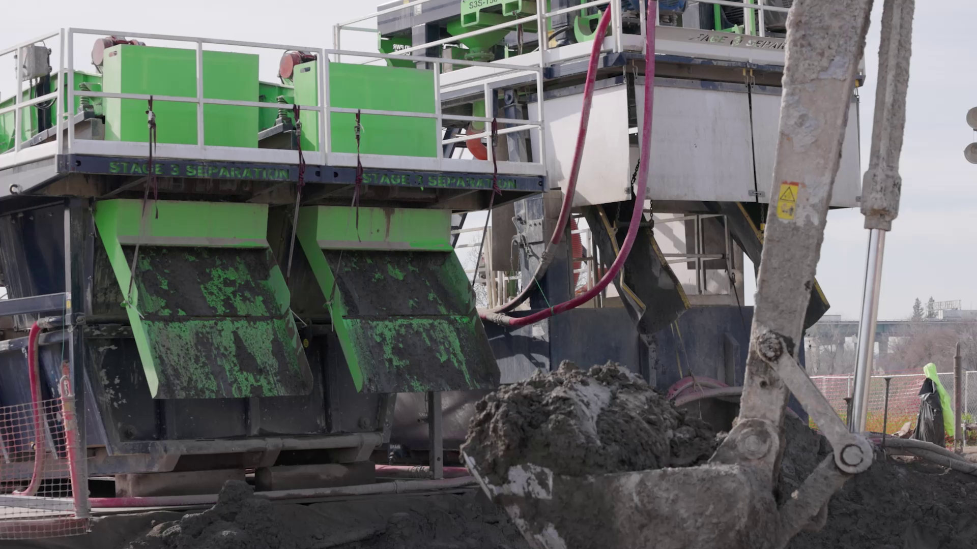
Onsite versus haul-off
Compare the whole waste pathway.
Direct liquid haul-off can be right for a small, brief, remote, or highly variable job. Onsite treatment earns a serious comparison when the volume, duration, site, and outlet pathways support the cost and complexity of a controlled plant.
Sustained volume
Mobilizing tanks, pumps, separation equipment, controls, and operators has a real cost. Compare it with total volume, peak feed, duration, shifts, interruption risk, transport, receiving fees, testing, and demobilization. One treatment day rate versus one truck rate is not a complete comparison.
Constrained logistics
Urban, tunnel, bridge, foundation, and active industrial sites can have limited staging and truck windows. Onsite treatment can change what moves offsite, but it still needs access, laydown, containment, solids loading, and a safe demobilization route.
A defined liquid pathway
Recovered liquid can have project value when it is suitable for process reuse or a defined next treatment step. Reuse is not automatic. Establish quality criteria, sampling, storage, and responsibility for the stream.
A defined solids pathway
Dewatering concentrates solids; it does not make contaminants disappear. Characterization, free-liquid testing, transportation rules, receiving-facility criteria, and beneficial-use requirements still apply.
A plan for variability
Geology, depth, additives, rain, concrete or grout contact, and operating practice can change the feed. Representative samples, expected ranges, and adjustment triggers are more useful than one ideal snapshot.
Project planning
Six inputs turn a slurry problem into an operating plan.
A useful review separates known conditions from estimates, closes the most consequential gaps, and defines how the project team will know that each output can move to its next step.
01
Define the source
Identify the activity creating the slurry and include known additives, possible contaminants, and how the feed changes through the shift or project phase.
02
Quantify the load
Provide instantaneous and average flow, daily or total volume, solids concentration, density, duration, and peak events. Mark measurements separately from estimates.
03
Characterize the solids
Use representative samples and particle-size data to distinguish sand, silt, clay, organics, cementitious material, and debris and to test the likely separation stages.
04
Set criteria for both outputs
Document the intended route, acceptance criteria, sampling, and approving authority for the liquid and solids streams before equipment is finalized.
05
Map the site
Confirm footprint, access, elevations, pumping distance, power, water, containment, operating restrictions, weather protection, solids loading, and truck movement.
06
Plan operation and proof
Set mobilization, staffing, spares, startup tests, normal operating window, adjustment triggers, reporting, shutdown, and demobilization assumptions.
S3S field applications
Different feeds. Different trains. The same scoping discipline.
These published applications show how S3S combined equipment and field operation around a specific slurry. They do not establish a universal reduction, discharge standard, or project saving.
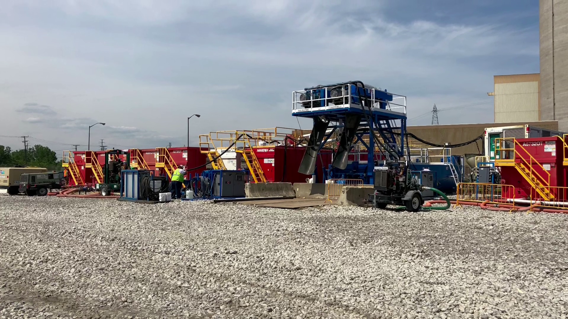
Polymer-fluid reuse at the Gordie Howe International Bridge
S3S's published account says BOS tanks, two large-bowl centrifuges, and an onsite technician processed solids-laden polymer slurry during drilled-shaft construction. The recovered polymer fluid was returned to the work, and vacuum trucks were used only for final tank cleaning. The transferable lesson is the operating loop: receive, separate, test rheology, adjust, and return fluid to the active process.
Jet-grout backflow in Midtown Toronto
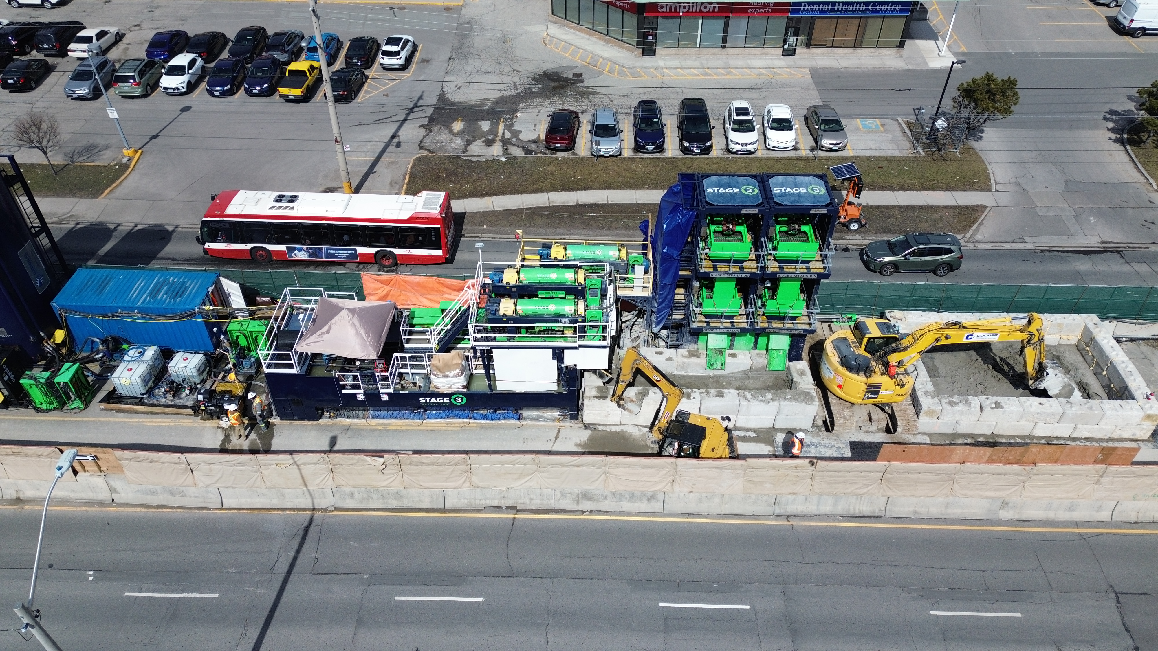
S3S's published Toronto Eglinton account describes a mobile tank, centrifuge, and flocculation system used where pit and truck space were constrained. The treatment separated a solids stream for haul-off and recovered water within that project's management plan. Because project quantities and acceptance criteria are site-specific, this example is presented as configuration proof rather than a performance guarantee.
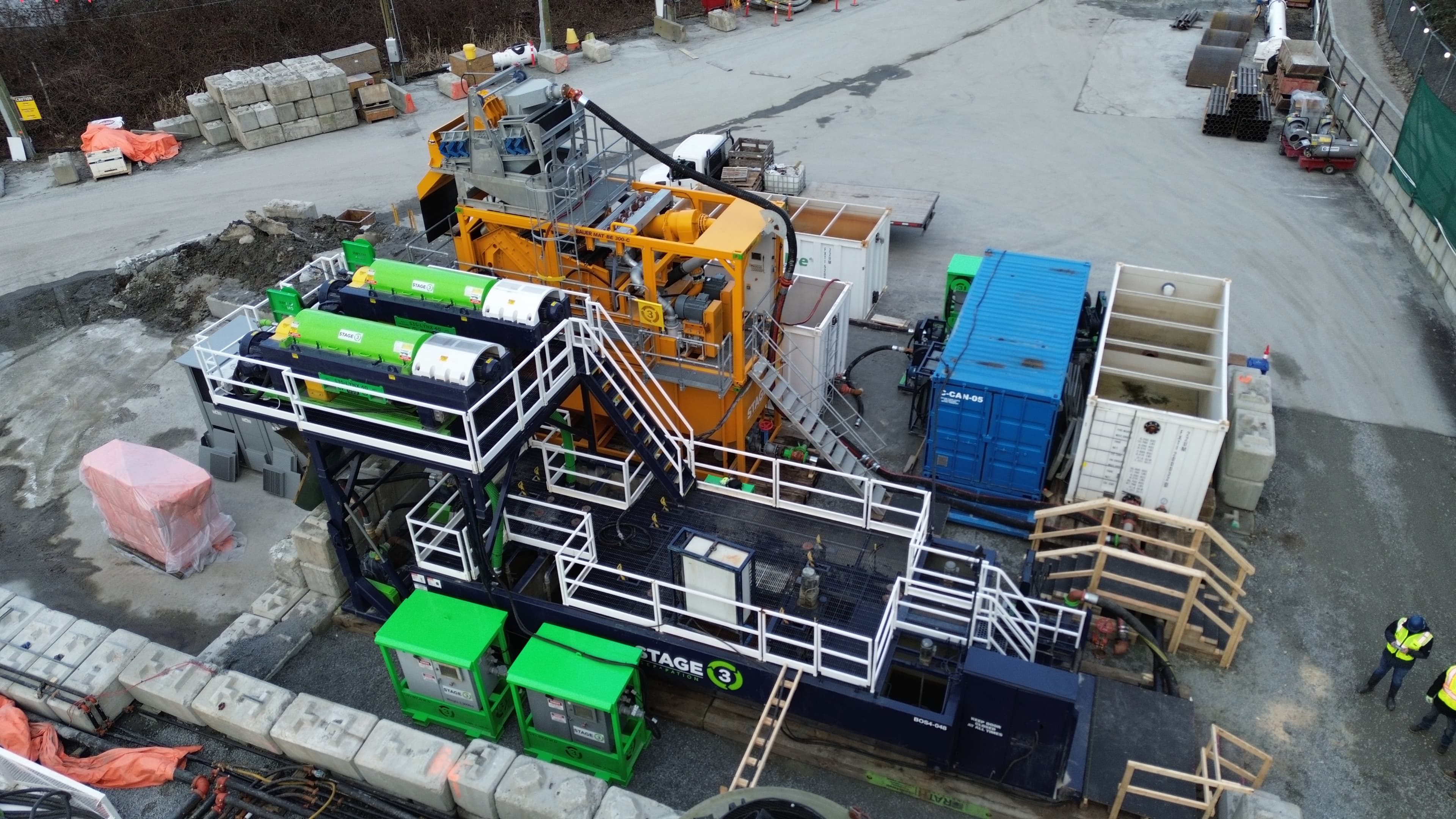
The BE 300-C inside a larger system
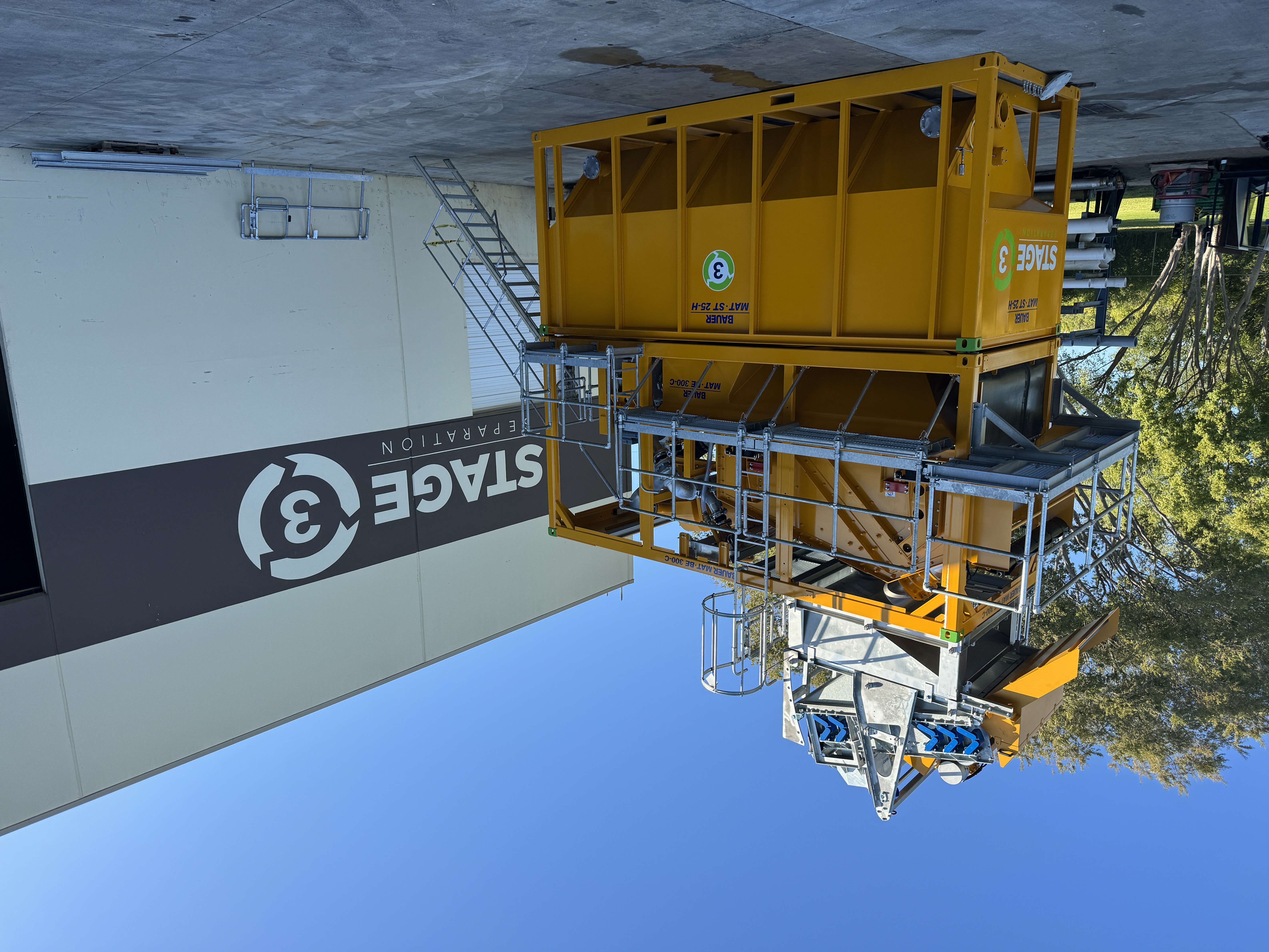
The BE 300-C gives S3S a documented high-volume scalping and desanding stage for construction, tunneling, dredging, mining, and industrial slurry. It does not replace the rest of the treatment decision. Fine-solids capture, chemistry, liquid routing, and solids handling are configured around the feed and project criteria.
Technical questions
What project teams ask before mobilization.
Not usually. Construction dewatering often means lowering or controlling groundwater so an excavation can proceed in the dry. Slurry dewatering means separating suspended solids from a process or waste slurry. One project can need both scopes, but the source water, equipment, permitting, and success criteria are different.
No. Coarse material may respond to screening and desanding. Some streams may fit settling, filtration, a press, geotextile containment, or direct haul-off. A centrifuge is valuable when continuous fine-solids separation fits the feed, rate, footprint, and output criteria. The train should follow the material.
The BE 300-C is a scalping and double-cyclone desanding plant. It removes coarse and intermediate solids and can protect downstream treatment. Whether its liquid output can be reused, needs a centrifuge or polishing step, or has an authorized discharge pathway depends on project-specific testing and criteria.
Conditioning may help when fine particles do not separate adequately through physical stages alone. The decision should come from representative testing and the intended outlets. Polymer selection and dose can change with particle surface chemistry, concentration, pH, temperature, mixing, and feed variability.
It is a handling description, not a permit or disposal approval. A receiving facility may require a specific test or solids condition. In the United States, EPA Method 9095B detects free liquids for particular RCRA provisions, but a passing result does not replace characterization or facility-specific acceptance requirements.
No. The project must define the intended use or receiving pathway and the applicable chemical, physical, biological, and administrative criteria. Sampling can show whether a stream meets a defined requirement; it does not create permission to reuse or discharge it.
A first project review draws on the slurry source, expected flow and total volume, duration, known solids, additives or contaminants, sample or lab data, intended liquid and solids pathways, site plan, utilities, schedule, and current haul-off or disposal approach. Uncertain values are marked separately so the review can focus on closing the right gaps.
Scope the full pathway
The feed, the site, and the required outputs set the treatment plan.
S3S will review whether onsite treatment is technically and commercially plausible, what additional testing is needed, where the BE 300-C or other separation stages may fit, and what operating assumptions should be resolved before mobilization.
What happens next
- A separation specialist reviews the slurry, the expected flow and the site.
- We size the equipment and the crew against your schedule and the outputs you need.
- You get a configuration and a scope you can price the job against.